+91 90049 90673

-
Products
AC To DC Module
 DC To DC Module
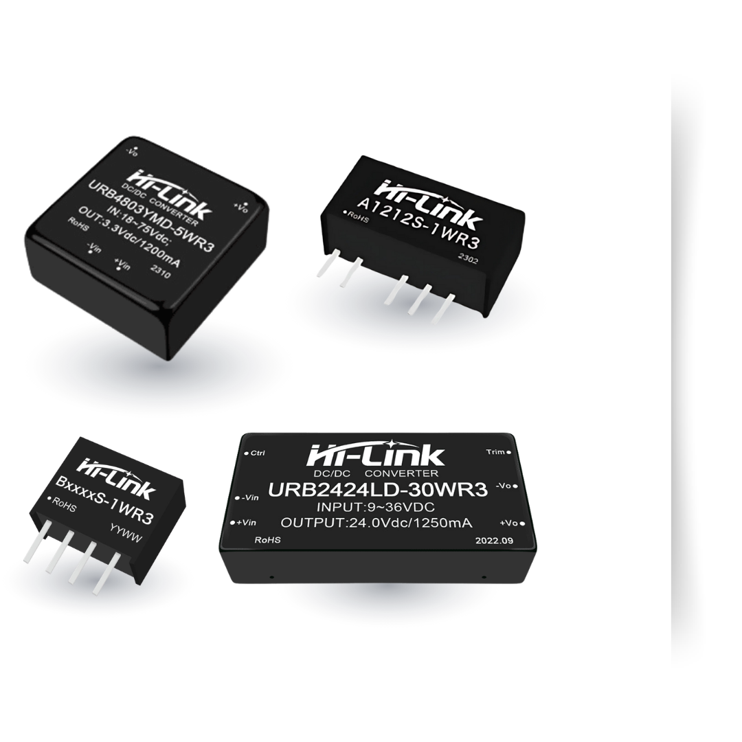 Radar Sensor Module
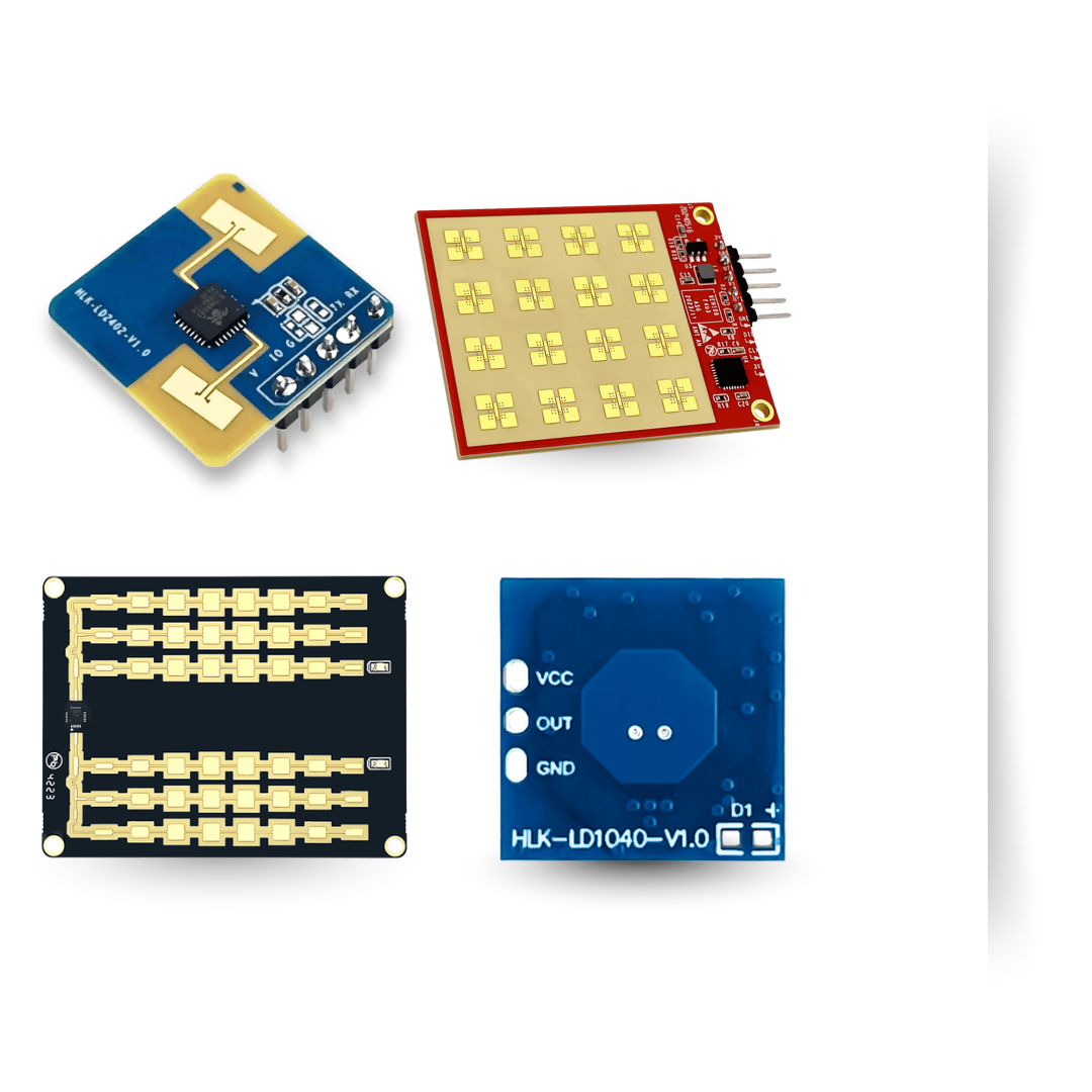 Wireless WIFI Module
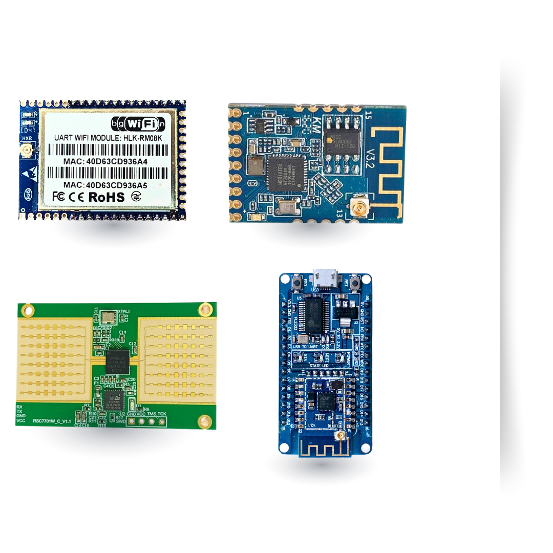 Finger Print Module
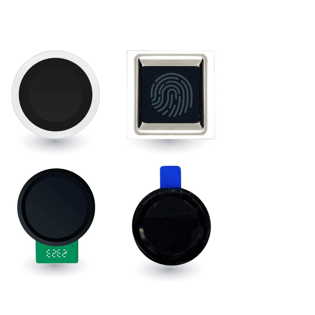
Menu
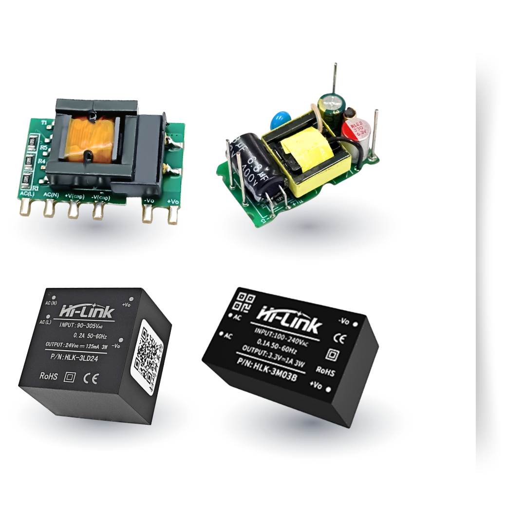
AC To DC Module
DC To DC Module
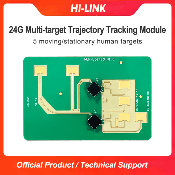
Radar Sensor Module
Wireless WIFI Module
Finger Print Module
Trending Search
Trending Products
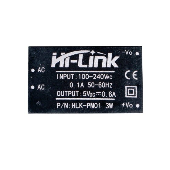
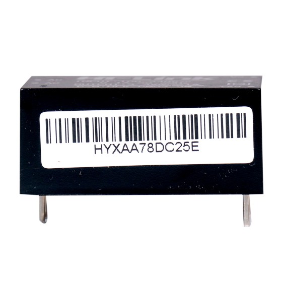
HLK-PM01 AC to DC 5v 3w Step Down mini Power Supply Module Converter Intelligent household switch power module
₹175.00
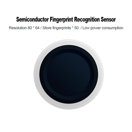
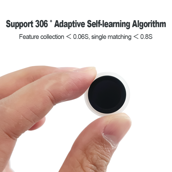
Hi-link fingerprint recognition module ZW101 low-power finger detection capacitive semiconductor fingerprint identification sensor module
₹257.00

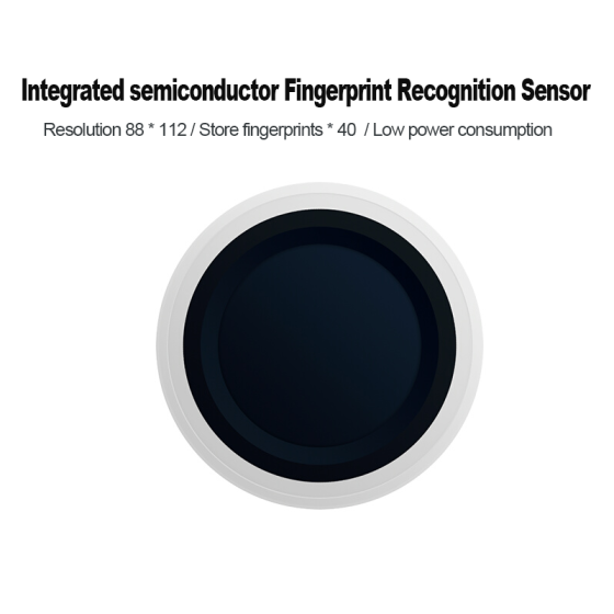
Hi-Link fingerprint recognition module ZW111 low-power finger detection integrated fingerprint sensor intelligent lock
₹277.00
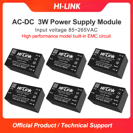

AC to DC 3W 3.3V/5V/9V/12V/15V/24V Step Down Mini Power Supply Converter Switch Power Module With EMC HLK-3M05C/3M12C/3M15C/3M24C
₹0.00
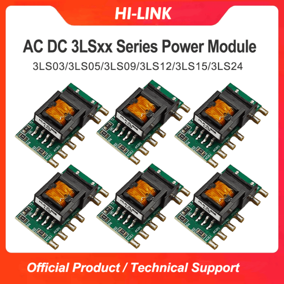
3LS03/3LS05/3LS09/3LS12/3LS15/3LS24 AC-DC 220v to 3.3/5/9/12/15/24V 3w Step Down Mini Power Supply Converter Module
₹128.00